Air leakage is defined as “air, other than exhaust air, return air and/or relief air that escapes from an air-handling system in an uncontrolled manner.”
The consequences of air leakage can include a reduction in delivered air flow; thermal losses due to air leaking between conditioned and unconditioned areas; and an increase in power consumption due to the additional capacity required to correct losses due to air leakage.
What our industry may not be aware of, however, are the levels of air leakage possible.
Air leakage standards
The standards commonly used in Australia and New Zealand that define air leakage requirements are:
- AS4254.2 2012 “Ductwork for air-handling systems in buildings Part 2: Rigid duct”
- BS EN1886:2007 “Ventilation for buildings – Air handling units – Mechanical performance”
- EN 13141-7:2017 “Ventilation for buildings - Performance testing of components/products for residential ventilation - Part 7: Performance testing of a mechanical supply and exhaust ventilation units (including heat recovery) for mechanical ventilation systems intended for single family dwellings”.
AS4254.2 2012 Clause 2.2.4 requires all duct systems with a capacity of 3,000 L/s or greater to be tested for air leakage at a static pressure of at least 1.25 times the calculated design operating pressure in the tested duct section. The air leakage is not permitted to exceed 5% of the design air quantity for the duct system. The standard requires that a minimum of 10% of each duct system be tested.
BS EN 1886:2007 defines how to test air handling units for air leakage and defines casing leakage classes for air handling units; L1, L2, and L3 (in order of best to worst air leakage performance). This standard calls for lower allowable air leakage as the filter class fitted within an AHU increases.
EN13141-7 is used to measure the air leakage of ventilation units including energy recovery units for single residential dwellings.
Air leakage testing process
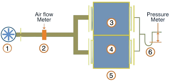
Performing an air leakage test is relatively simple. The air inlets and outlets are capped and air is pumped into the system until a specified pressure is achieved. The air flow continues and is then measured. This airflow rate reflects the amount of air that is leaking at the specified pressure drop. As the system pressure increases, the amount of air leakage will also increase.

Figure 1: Example test setup for external air leakage testing
Key:
-
1 Adjustable fan
-
2 Air flow measuring equipment
-
3 Exhaust air side
-
4 Supply air side
-
5 Heat recovery device
-
6 Static pressure measuring equipment
Physical test results:
Energy recovery unit
An air leakage test was recently performed on a heat recovery unit (HRV) to EN 13141-7.
When subjecting the HRV Unit to +300 Pa, 111 m³/hr of external air leakage was recorded. As the HRV is rated to 180 m³/hr the test indicated 61.8% air leakage. When -300Pa was applied to the HRV unit, an air leakage rate of 64.9% was recorded.
The internal leakage defines the air leakage between the supply air and exhaust air compartments of a heat recovery unit. This test measured 76.7% when a pressure differential of 100Pa was applied. This creates at least a couple of significant issues:
- True heat recovery performance is extremely poor because much of the air by-passes the heat recovery process.
- The fresh air supply is likely to be contaminated by exhaust air. This is problematic when extracting from bathrooms (odour and humidity), and with general recirculation of contaminants such as CO 2 and VOC’s.
| External Overpressure Leakage |
|
External Underpressure Leakage |
|
Internal Leakage |
| Reference flow |
180 |
(m³/h) |
|
Reference flow |
180 |
(m³/h) |
|
Reference flow |
180 |
(m³/h) |
| Ref static pressure |
50 |
(Pa) |
|
Ref static pressure |
50 |
(Pa) |
|
Ref static pressure |
50 |
(Pa) |
| P (Pa) |
q ve (m³/h) |
q ve/q vd (%) |
|
P (Pa) |
q ve (m³/h) |
q ve/q vd (%) |
|
P (Pa) |
q ve (m³/h) |
q ve/q vd (%) |
| 100 |
59.8 |
33.2 |
|
-100 |
60.5 |
33.6 |
|
50 |
92.5 |
51.4 |
| 250 |
100.3 |
55.7 |
|
-250 |
105.3 |
58.5 |
|
100 |
138.1 |
76.7 |
| 300 |
111.2 |
61.8 |
|
-300 |
116.8 |
64.9 |
|
200 |
- |
- |
| Table 1: Air leakage test results of sample HRV unit. |
q ve
= external air leakage (air flow leaking between the internal and external of the HRV unit at a test pressure).
q vi
= internal air leakage (air flow leaking internally between the supply air and exhaust air sections of the HRV unit at a test pressure).
q vd
= declared air flow rate.
VAV box and duct run
An air leakage test was recently performed on a length of ductwork and a VAV box to AS4254.2 2012.
The results of the test showed that the VAV Box component of the system had 9% air leakage of the designed air flow rate (design air flow = 3,000L/s, VAV air leakage = 270 L/s). Because the VAV Box exceeded 5% air leakage the total system failed due to this single part of the ductwork, without considering further leakage from the remainder of the duct system.
Potential weak points
Air leakage can be improved by paying close attention to the product’s construction. Potential weak points for air leakage include:
- Slip on flanges, such as Mez flanges, ductmate or Wards flanges
- Inadequate size and/or application of gasket seals
- No silicon sealant along seams
- Poor sealing of panels on AHU units
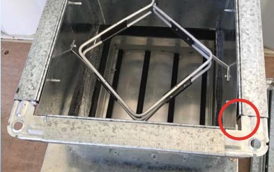
If you can see any holes, gaps or poor joins then you will most likely have air leakage at these locations.
 Figure 2: Sample duct section highlighting potential air leakage paths.
Conclusion
Many engineers are unaware of the volume of air leakage in ductwork systems that include multiple components. The amount of air leakage from a piece of equipment is often closely related to the quality of the unit’s construction. A unit that appears to be of poor construction quality is likely to have more air leakage.
If a product has been air leakage tested and achieved a low leakage rating (such as L1), this suggests that care has been taken with the design and construction of the unit in order to minimise air leakage.


